Error code FC1 on Haier washing machine
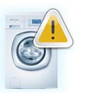
 There are times when a fault code appears on the “home assistant” display, and the machine itself automatically stops working and does not resume until the problem is fixed. Such a signal indicates a problem with the control module, so the first thing the housewife should do is disconnect the unit from the power supply for 5 minutes and then turn it on again. If restarting does not help, you will have to diagnose the control module. Today we will find out why error FC1 may occur on a Haier washing machine.
Elements of the control board of the SM Hier module
When you first look at the washing machine's control module, you will be very surprised at how many semiconductor elements it contains. Error code FC1, unfortunately, does not indicate a specific fault, so checking each part will take a lot of time. For this reason, it is important to know which sensors are responsible for which functions. This will help you quickly detect and fix the defect.
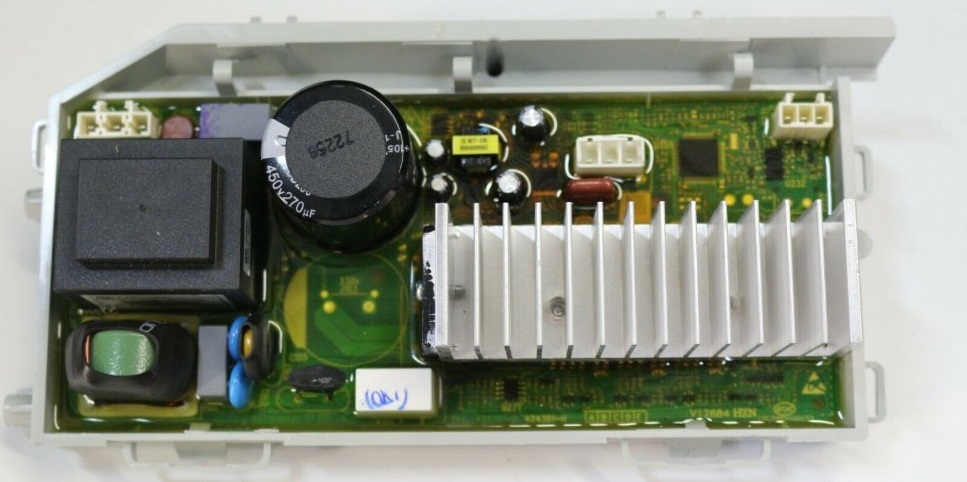
A standard control module consists of two main parts: a control panel and a power unit. To access the board itself, you need to disassemble the corresponding part. Under the protective casing and compound there are semiconductor elements responsible for controlling the operation of various components of the washing machine. On the left side of the module there are parts that are responsible for powering the unit. These include:
- integrated stabilizer KIA7805, designated U14;
- pulse converter based on PWM controller STR-A6059M;
- mains rectifier and filter (BD1 and CE4);
- protective varistor (Z2);
- mains fuse;
- key converter chip (designated U12);
- SMPS – aka pulse transformer;
- diode D13, capacitor CE2;
- diode D11, capacitor CE8, power channel 9V;
- diode D12, capacitor CE9, 12V;
- diode D14, capacitor CE6, power channel 12V;
- diode D6, zener diode ZD1, transistor Q1, resistor R103;
- resistor R74, also known as 205;
- optocoupler U15, transistor assembly U3;
- U13 processor;
- relay X1, which is connected to the heating element circuit;
- integrated voltage stabilizer 5V, designated U.
Let's move on to the next element on the control board. It interfaces with a temperature sensor and includes the following semiconductors:
- pin 4 (TH1) of connector RD6;
- resistor R12;
- 37 processor leg U
The functioning of the heating element is influenced by the following semiconductors: relay X1, 64 leg of processor U13, 1 and 16 legs of assembly U3, relay X2, 24 leg of processor U13 and transistor Q7. In addition, the module has a backup relay control channel. Components are installed optionally. We are talking about the following semiconductors:
- 75 processor leg U13;
- resistor R83;
- transistor Q5;
- relay X4;
- second pin of connector BL.
It is worth noting that resistors R6, R7, 67 of the U13 processor leg play an important role in ensuring stable operation of the pressure switch!
The next block of semiconductors controls the operation of the prewash compartment valve. These include: 29 leg of the processor U13, 4 and 13 legs of the assembly U3, resistor R25, R29, optocoupler U8, triac TR3, pin 1 of connector YL4. The following are responsible for the operation of the main wash valve: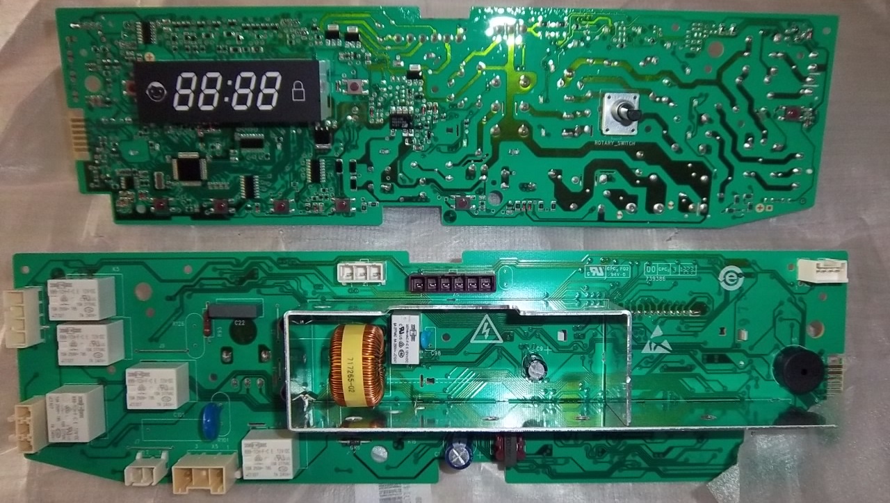
- 31 U13 processor legs;
- 6 and 11 legs of assembly U3;
- resistor R23, R27;
- optocoupler U6;
- triac TR5;
- pin 4 of connector YL4.
The following circuit provides control of the hot water inlet valve: 31 processor legs U13, 6 and 11 legs of the U3 assembly, jumper J1, resistor R24, R28. As well as optocoupler U7, triac TR4 and the second contact of connector YL4. The operation of the drain pump is influenced by semiconductors such as:
- 61 U13 processor legs;
- resistor R77, R79, R82;
- transistor Q4, Q3;
- optocoupler U4;
- triac TR20;
- pin 4 of connector BL4.
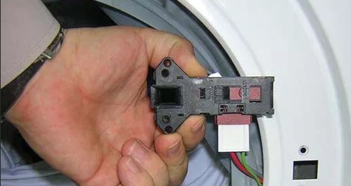
If problems arise with the washing machine hatch locking mechanism, you should pay attention to the following set of elements: 27 processor leg U13, 2 and 15 assembly legs U3, resistor R21. This also includes optocoupler U2, relay X3 and pin 1 of connector BL4. The Hall sensor, which controls engine speed, is responsible for the operation of:
- pin 4 and 6 of connector BL6;
- resistor R44, R60;
- 3,4,5,6 legs of U1 chip;
- 19.20 processor leg U
There are situations when the “home assistant”’s motor suddenly stops functioning. This can happen due to problems with the power supply, when, for example, there is a short circuit or an overload of the power supply. In order to identify a breakdown, check the following circuit:
- 17 processor leg U13 – power assembly HS1 (output stages and drivers) – microcircuit U1;
- comparator from the U11 microcircuit – storage choke RA – resistor R58, R57;
- 6.7 legs of comparator U11 – control of the supply voltage of 300V, the signal goes through a circuit with the diode assembly BD1, resistor R70 and 41 legs of the processor U.
The operation of the program switching selector is controlled by resistors R73, R72 and 73, 74 legs of the U13 processor. These elements are used to regulate electrical signals and provide protection against short circuits and overloads. Their serviceability is necessary for the efficient operation of the entire system.
As you can see, there are quite a few semiconductor components that can make repairing a control module a challenging task. Especially for beginners who have no experience working with microcircuits. If you are familiar with resistors, relays, optocouplers and have an idea about building electrical circuits, you can try to restore the unit yourself.
How is a module repaired?
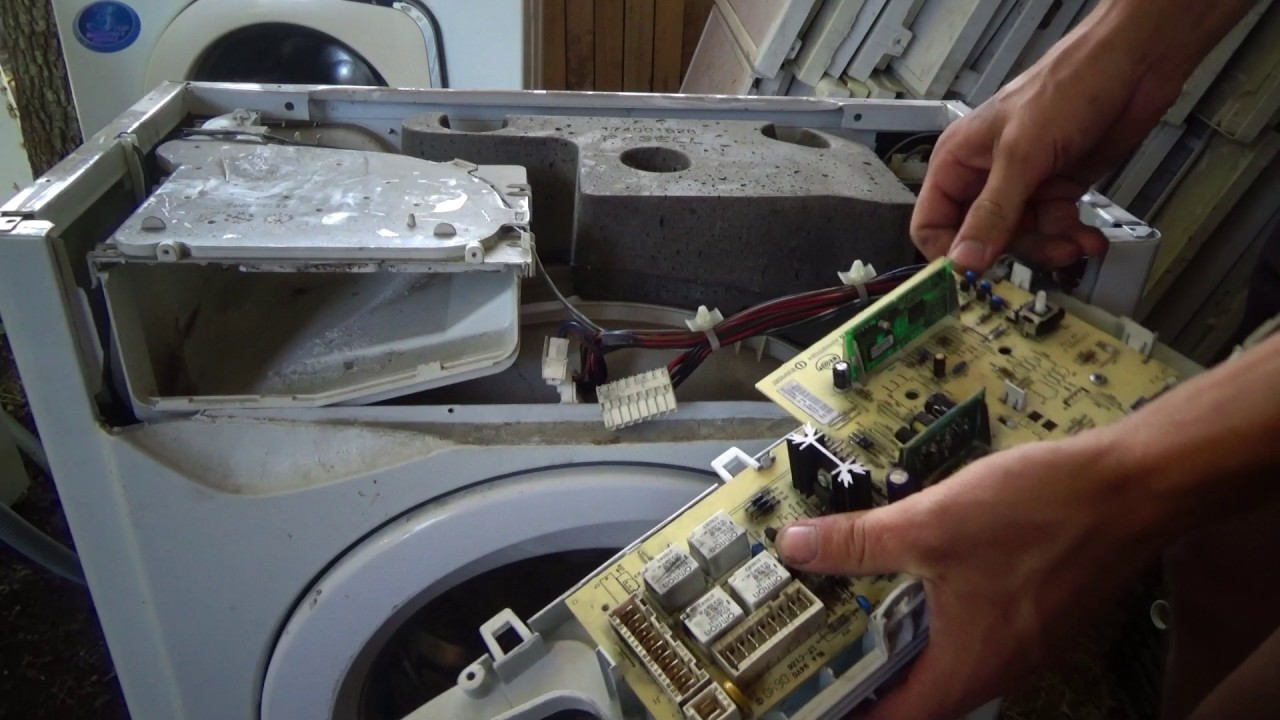
Analysis and restoration of the washing machine control unit is complicated by the presence of a compound on the board. In addition, the module is often covered with a casing that must be removed before starting work. The sequence of actions will be as follows:
- using a slotted screwdriver, move around the perimeter of the casing from the inside to clean the edges of the board from the sealant;
- make a deeper groove in the gap between the board and the casing;
- insert a thin screwdriver into the corner where the mains transformer is located;
- lift the block and pull it out.
Your actions must be extremely careful, as there is a high chance of harming the microcircuit. Once you have removed the board, you should remove any remaining sealant from it and make repairs to the area that needs it. Usually the damaged element is soldered off and replaced with a new one. Next, you will need to resort to a protective varnish and cover a certain area with it. In this case, you can use Plasik70, which is intended for installation work.
Professionals prefer not to completely open the protective casing and simply make a cutout in it, which simplifies access to the damaged part. For example, the master understands that the cause of the malfunction lies in the semiconductors that control the operation of the drain pump.To avoid having to remove the entire casing, he makes a cutout in the lower right corner to check the parts he needs.
When working with the electronic module of a Haier washing machine, extreme caution must be exercised. Removing the board from the casing always involves a high risk of damaging the chips. Therefore, if you do not have confidence in your own skills, the most reasonable solution would be to seek help from a service center that specializes in repairing household appliances.
Interesting:


Reader comments
- Share your opinion - leave a comment
Categories
Washing machine repair

For buyers


For users


Dishwasher

Add a comment