Reverse on the washing machine motor
 According to statistics, the most “serious” failures of washing machines are failure of the electronic module and wear of the bearing unit. The remaining problems, although they occur more often, are easy to fix. Even if the “home assistant” is hopelessly broken, its “heart”, namely the motor, usually continues to work properly and can be reused.
Therefore, the motor from the washing machine is often used in the manufacture of various machines: emery machines, lathes, etc. In order for the homemade device to function properly, it is necessary to reverse the motor from the washing machine. Let's figure out how to do it ourselves.
We'll collect everything you need
During the work on connecting the electric motor and ensuring its reverse, special devices and tools will be required. To check the electrical circuit, a standard multimeter is useful. You can purchase a tester in specialized stores.
In addition, the process will require: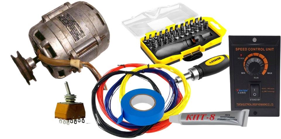
- toggle switch (electric current switch) 220 Volt, 15 Ampere;
- motor speed controller;
- wires of different colors (it is recommended to use blue (zero) and brown (phase));
- the electric motor itself (an engine from any old automatic machine will do);
- insulating tape;
- screwdrivers;
- packaging of heat-conducting paste.
Of course, you should have other materials on hand that are necessary to construct a homemade device. When all the equipment is prepared, you can start working.
Powering the motor
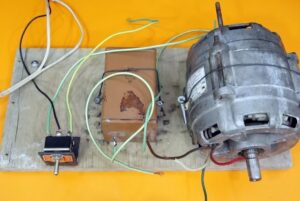
First, carefully examine the dismantled electric motor. The collector usually has 6 terminals: two for connecting a tachometer and a pair of wires for the stator and rotor windings. The tachogenerator will not be useful outside the washing machine, so these contacts can be immediately discounted.
To power a single-phase motor, it is necessary to connect the output of the stator and the beginning of the rotor winding, and connect the other ends to the zero contact and phase.
To determine the winding terminals on the plug, you will need a multimeter. One tester probe should be applied to the terminal, and the free one should be placed alternately against the other contacts. If the ohmmeter signals a short circuit, it means that two terminals are connected to the same electrical winding.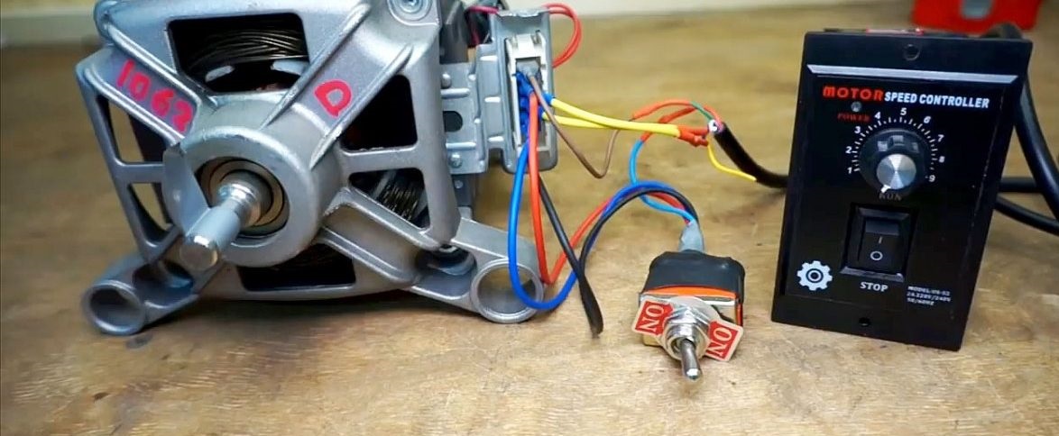
When everything is in order, you can apply standard 220-volt voltage to the motor. In a normal situation, the engine will start working and begin to rotate unilaterally - counterclockwise or clockwise.
How to ensure reverse rotation?
Reversing an electric motor is a change in the rotation of the rotor to the opposite direction. To ensure this process, you need to change the position of the ends of one of the windings. Then the motor will start moving in the other direction.
In order not to constantly interfere with the circuit and rearrange the winding wires, it is better to install a special device. The direction of rotation of the rotor can be switched by clicking a toggle switch. The connection is easy to do yourself.
To begin, turn the toggle switch over and examine the markings on the bottom of the device. There are designations for all outputs, and a connection diagram for different switch positions (right and left) is also presented. To make it easier for you to understand, sketch out an elementary circuit: two motor windings and a pair of switch contacts. The middle wires are alternately connected to the side wires.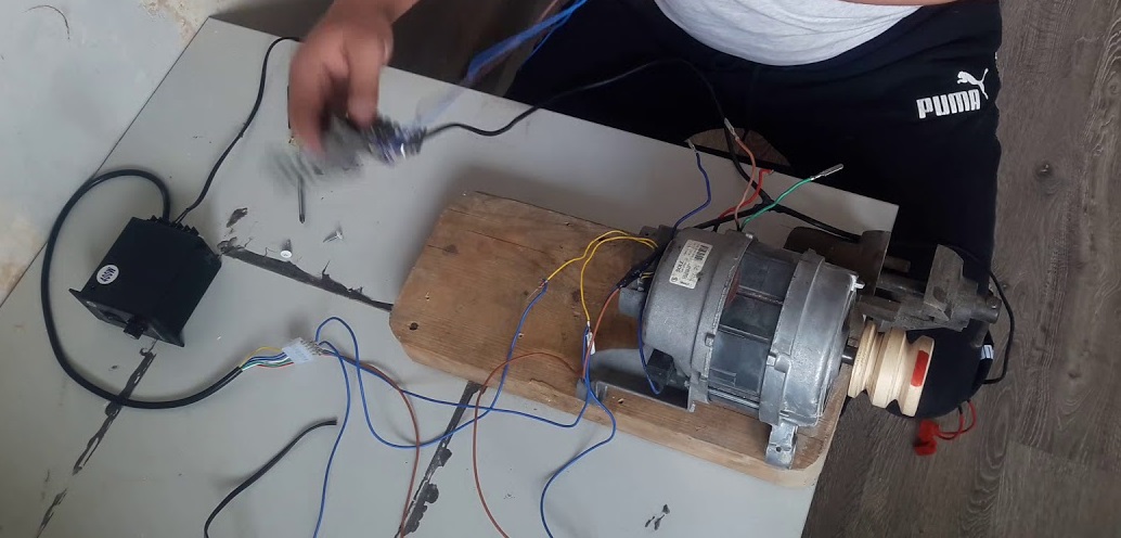
The output of one electrical winding must be connected to the lower contact located on the edge and aligned with a jumper with the outermost terminal located on top. Connect the stator winding wire to the connector located in the middle.
Next, the only thing left to do is to include the rotor in the circuit. The output of the rotor winding must be connected to one contact of the commutator, and the neutral supply wire to the other, remaining one. After this, it is necessary to organize diagonal jumpers between the two outer terminals. The first middle terminal of the toggle switch is connected to the “zero”, the second – to the “tail” of the rotor winding.
After finishing the circuit, be sure to make sure that all contacts are connected correctly.
In short, the middle contacts of the mechanical switch must be connected: one to the neutral wire, the second to the stator electrical winding. The opposite “tail” of this winding is connected to the phase (brownish-colored wiring). It is imperative that the diagonal contacts are connected by jumpers and the wiring from them is carried out to the rotor winding.
Before starting the engine, arm yourself with a multimeter. Using a tester, check how the short circuit changes when the toggle switch is clicked. Be sure to insulate all contacts. You can switch the direction of rotation of the motor only when the rotor comes to a complete stop. Therefore, do not rush to click the toggle switch, wait until the element stops spinning.
How to increase engine speed and reduce it?
The motor speed controller can be ordered on the well-known Aliexpress website. It is worth understanding that cheap products from China do not always correspond to the declared quality, so be sure to diagnose the device.Remove the internal “stuffing” from the case and carefully inspect the triac. If you're lucky, it will have a small heatsink that barely does its job of preventing overheating. In the worst case, it won’t be there at all, then you’ll have to buy the part separately.
On an “imperfect” radiator you will have to cut an M3 thread. Then apply a little thermal paste to the surface of the triac and fix the improved heat exchanger in its original place. Then reassemble the regulator.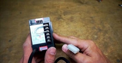
Behind the device there is a strip with several connectors and terminals. All exits are signed. It is necessary to find the neutral contact, phase and ground, and the corresponding cables are connected to them.
The purpose of each output and the corresponding wire color should be described on the top panel of the speed controller housing.
Typically, the yellow output wire is ground, a pair of blue ones are pins for connecting a tachometer, and bright red is a phase. The snow-white and green contacts are interchangeable, which is regulated by a jumper. You can determine the resistance of the terminals by testing them with a multimeter.
Once you understand the device, connect it to the engine. Check that the wires are connected to the correct terminals. When finished, apply 220-volt voltage to the electric motor speed controller. Now it’s easy to switch the speed and rotation modes of the engine with your own hands.
There is also a special hole on the walls of the controller. It is designed to adjust the operating modes of the electric motor with a variable resistor. You can set the step for changing the motor speed. Then, when the chain starts, the rotation of the rotor will not be “jerky”, but will start smoothly, almost from scratch.
Interesting:


")


Reader comments
- Share your opinion - leave a comment
Categories
Washing machine repair

For buyers

For users


Dishwasher
Add a comment